Rigid-Flex PCB Manufacturing Services
Rigid-flex boards integrate rigid sections for component density with flexible regions for dynamic bending or folding—ideal when connectors and harnesses must disappear.
Service overview
Successful rigid-flex programs document bend radii, stiffener placement, coverlay openings, and adhesive systems. We review those details with your mechanical and electrical owners before release.
Rigid-flex is a core specialization for MOZPCB. Each quote includes a review of the flex stackup—polyimide core and coverlay selection, adhesive versus adhesiveless constructions, and whether your bend zones are static (fold-to-install) or dynamic (repeated flexing)—because those choices drive both reliability and cost.
Applications span wearables, portable medical devices, and industrial equipment where vibration and repeated motion demand disciplined flex regions.
What we offer
- Rigid-flex structures with documented bend zones and stiffener strategy
- Constructions from simple 2-layer flex with rigid caps to multilayer rigid-flex with buried flex layers
- Flexible circuit sections processed with appropriate coverlay and access openings
- Adhesiveless polyimide constructions for tighter bends and higher reliability where specified
- Space-saving layouts that reduce connectors, harnesses, and hand-soldered jumpers between rigid subsystems
- DFM guidance on pad anchors, tear drops, and strain relief near flex transitions
- Stiffener options in FR-4, polyimide, and stainless steel per your drawings
- Assembly of rigid-flex boards including fixturing for non-flat panels
Technical capabilities
- Static bend designs typically down to 10x flex thickness; dynamic bends reviewed case by case
- Multiple flex arms, air gaps, and bookbinder-style constructions (design-dependent)
- Flex layer counts from 1 to 6+ within rigid-flex stackups, subject to design review
- Selective stiffeners and PSA attachment when drawings specify them
- Impedance-controlled flex segments when stackups support it
- ZIF connector tail thickness control and gold plating for direct-insertion tails
- Coverlay openings, dams, and windowing aligned to your assembly plan
Common applications
- Wearables and hearables with dynamic motion
- Medical electronics with articulated probes or patient interfaces
- Foldable and hinged consumer devices where cables cannot fit
- Industrial control devices exposed to vibration and thermal cycling
- Aerospace instrumentation where weight and connector count must fall
How the process works
- 01
Requirements intake
Share Gerber, BOM, drawings, quantities, and any reliability or compliance notes.
- 02
Technical alignment
We confirm materials, finishes, assembly flow, and test expectations with you.
- 03
Production & inspection
Manufacturing and assembly follow the agreed traveler with documented checks.
- 04
Delivery
Packing, labeling, and shipment according to your logistics instructions.
In our factory
-
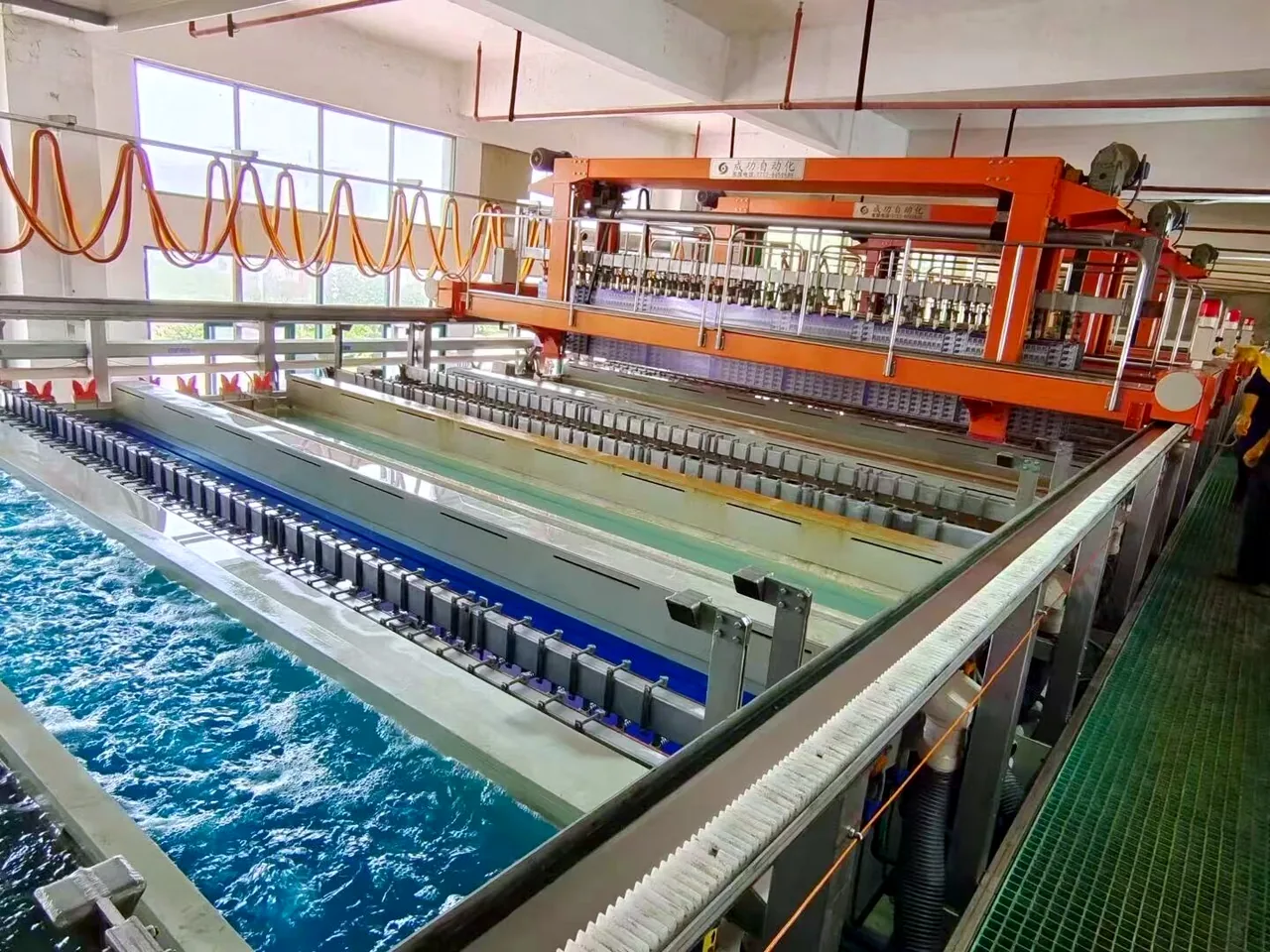
Plating line -
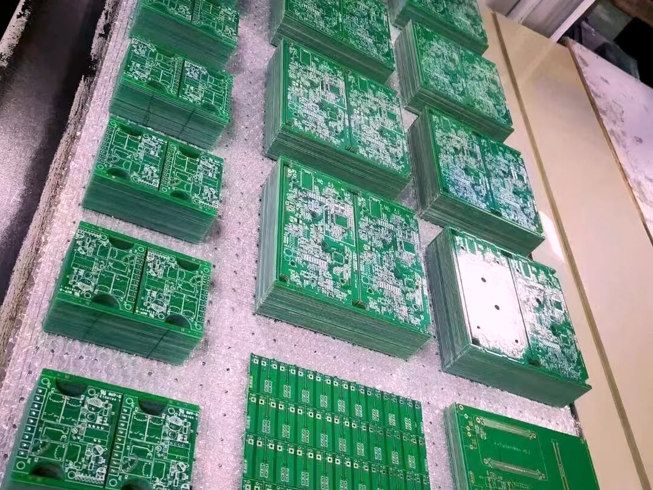
Panelized boards -
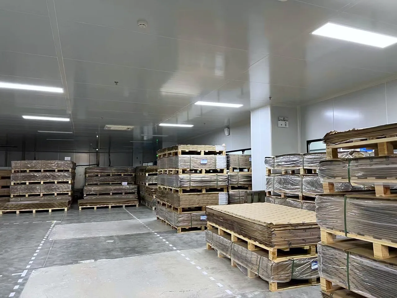
Laminate store
Related services
FAQ
What mechanical information is most important for rigid-flex?
What is the minimum bend radius for a rigid-flex PCB?
How does rigid-flex compare in cost to a rigid board plus cables and connectors?
Do you support both static and dynamic flex applications?
Can rigid-flex include impedance-controlled layers?
Get started
Ready for the next step?
Send your project files and requirements. We will review stackup, assembly, and test needs, then respond with a clear quotation path.